Aim
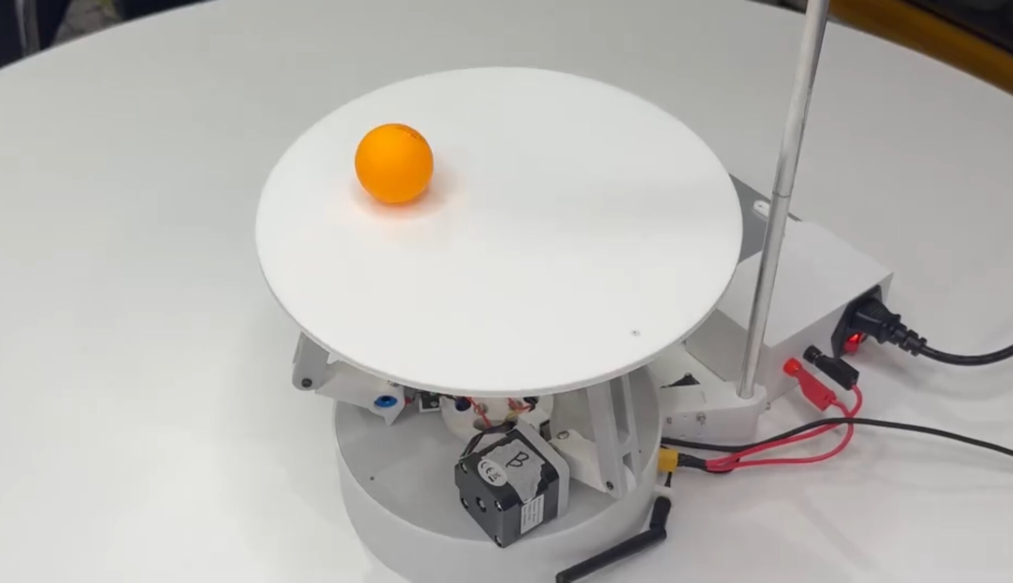
- To build a robot capable of balancing a ball on a platform indefinitely, with <1mm steady-state error
- Keep the total cost under $150 by only using ESP32-based hardware
Result
- Achieved <1mm steady-state error during balancing
- Developed a 40 FPS ball detection algorithm running on a ESP32
- Integrated control panel with live telemetry, allowing users to intuitively explore PID behaviour
- Won the 10K Club Competition, securing $10,000 to continue developing the project
How?
1. Electronics
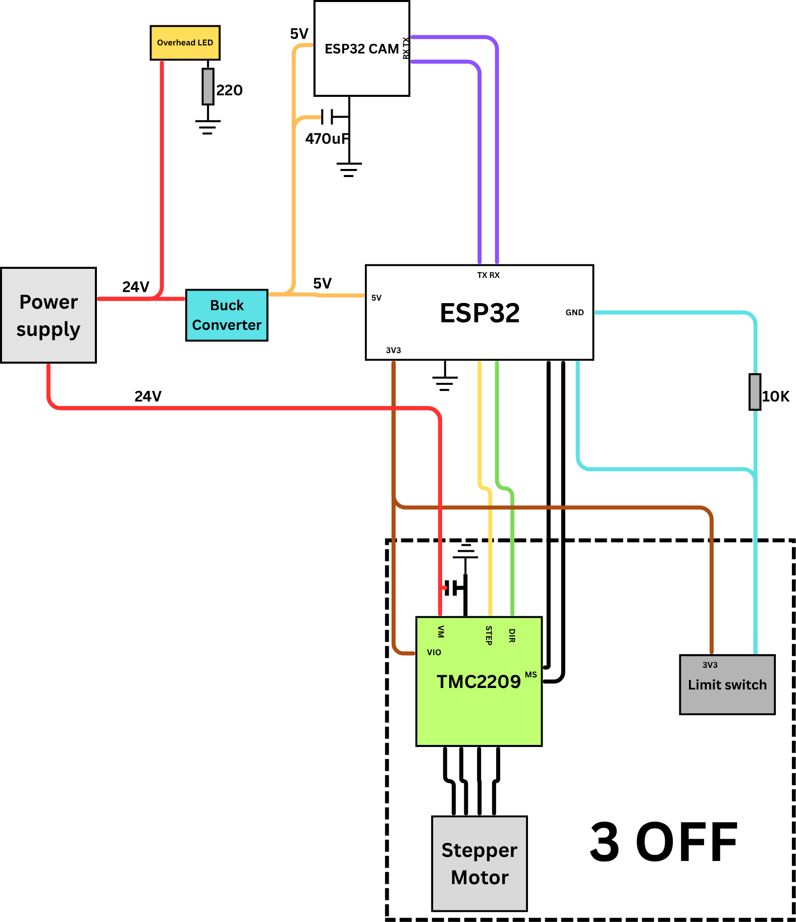
Wiring Diagram
- The electronics are built around an ESP32 microcontroller that performs real‑time PID updates, issues motor commands, and communicates with the vision system.
- Each actuator is driven by a TMC2209 stepper driver, supplied with a 24V poer supply and a buck converter
- A custom PCB integrates the ESP32, stepper drivers, power regulation, limit‑switch inputs, and filtering components into a compact, noise‑resistant layout.
- A dedicated ESP32‑S3‑CAM mounted above the platform handles image capture and processing, sending ball‑position data to the main controller over serial.
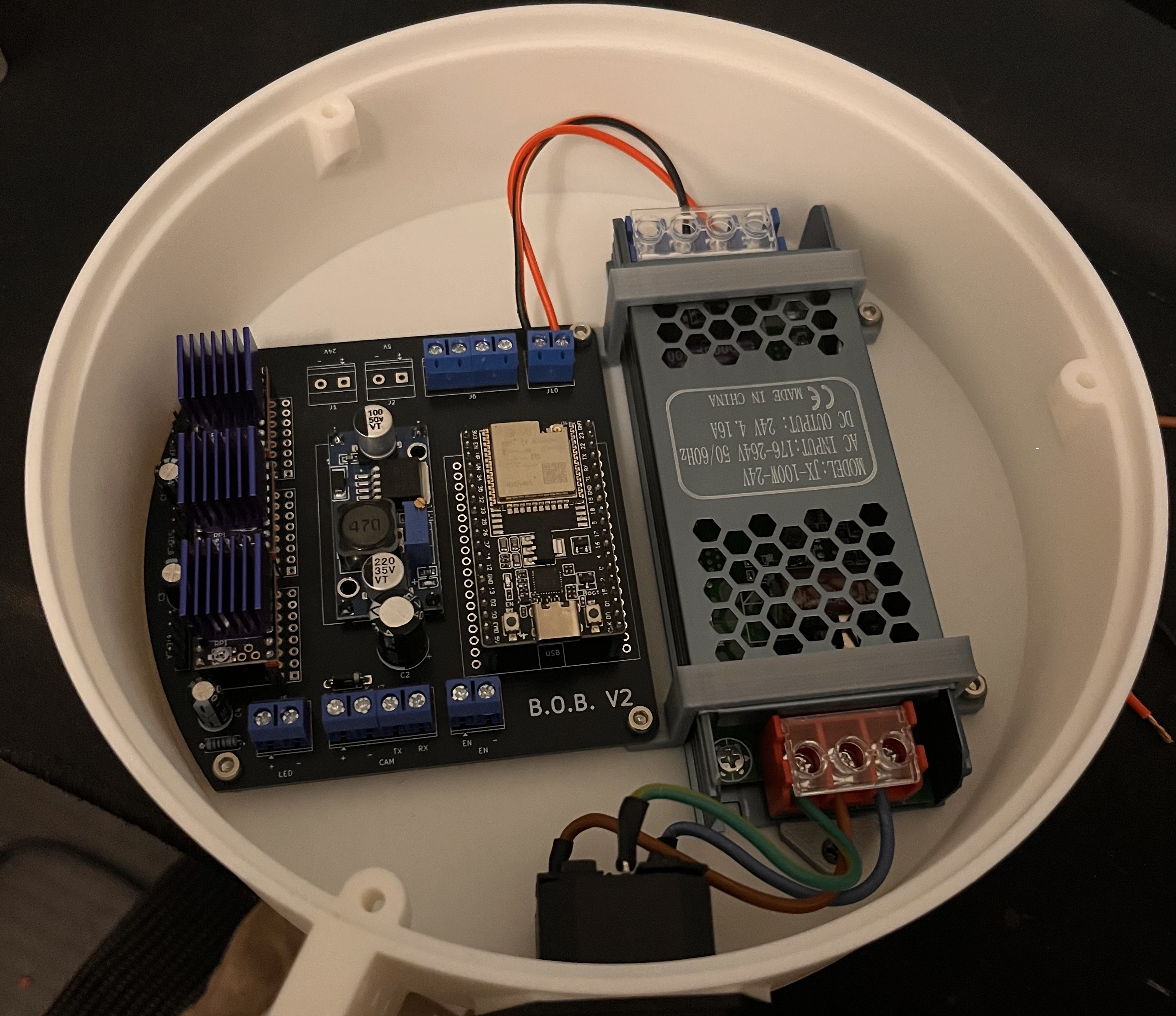
Final Internals
2. Software
- The B.O.B. system comprises three primary subsystems: a vision module, a central processor, and a user interface.
- An ESP32-CAM mounted on top of the robot, pointing down, utilises computer vision to detect the location of the ball and continuously sends this data to the main ESP32.
- The ESP32 uses the coordinate data stream to run a PID controller and inverse kinematics to control three motor drivers, which, in turn, move stepper motors to tilt the platform to a desired position to balance the ball.
- Simultaneously, the main ESP32 wirelessly exchanges data with a laptop connected to its access point, allowing the user to monitor and control the robot.
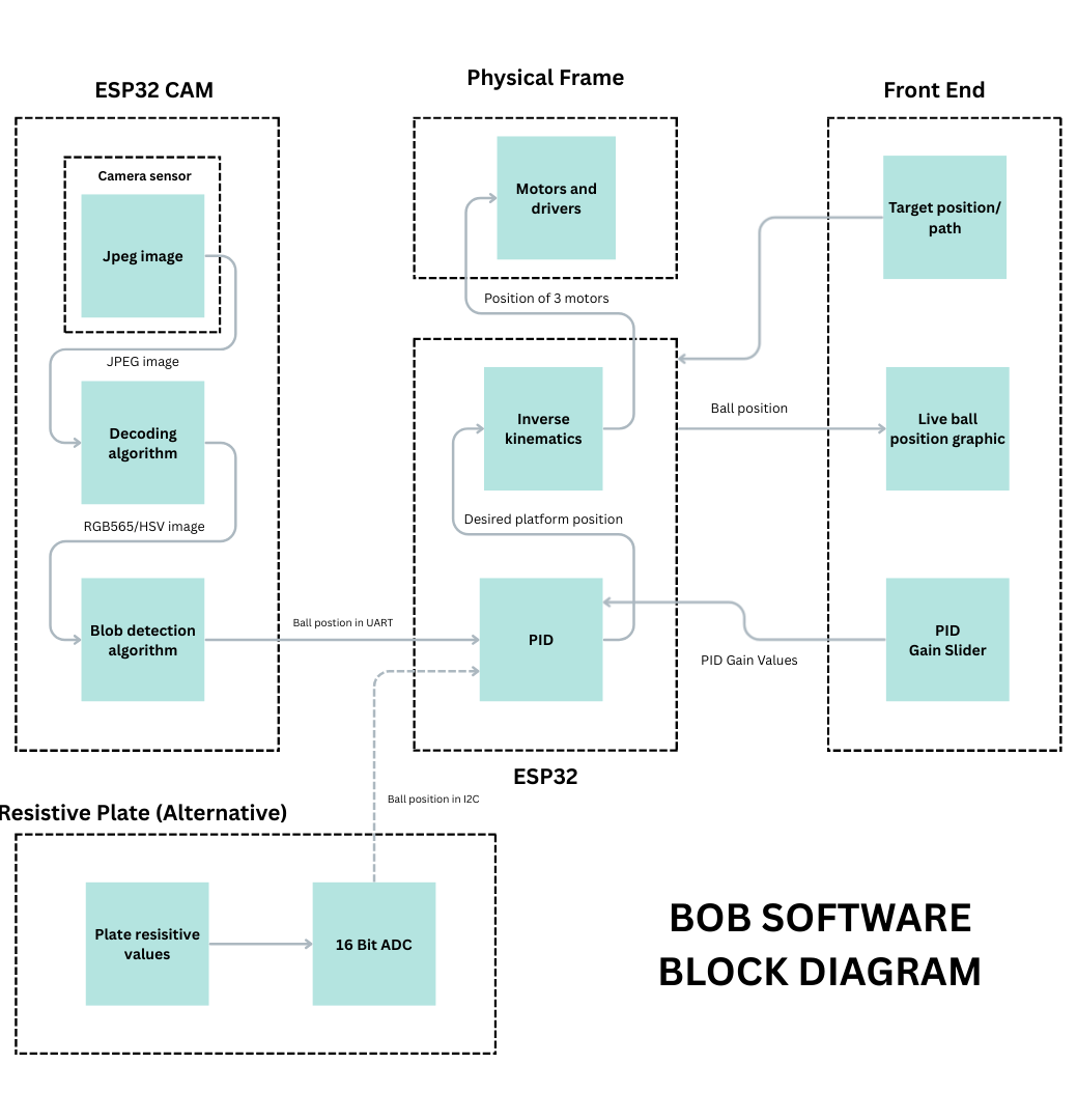
a, Vision System
- The ESP32‑S3‑CAM captures images at 40 FPS in JPEG format at 240×240 resolution before decoding them to RGB565 for processing.
- Every fourth pixel is converted to HSV and compared against calibrated thresholds to isolate the orange ball.
- The coordinates of all detected pixels are averaged to compute the centroid, which is transmitted to the main ESP32 via UART.
- To ensure reliable detection under varying lighting, a high‑intensity LED was added to stabilise colour readings
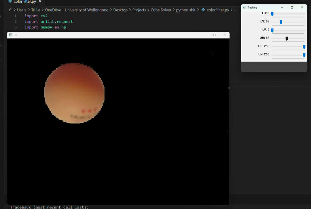
HSV Analysis
b, Control and Firmware
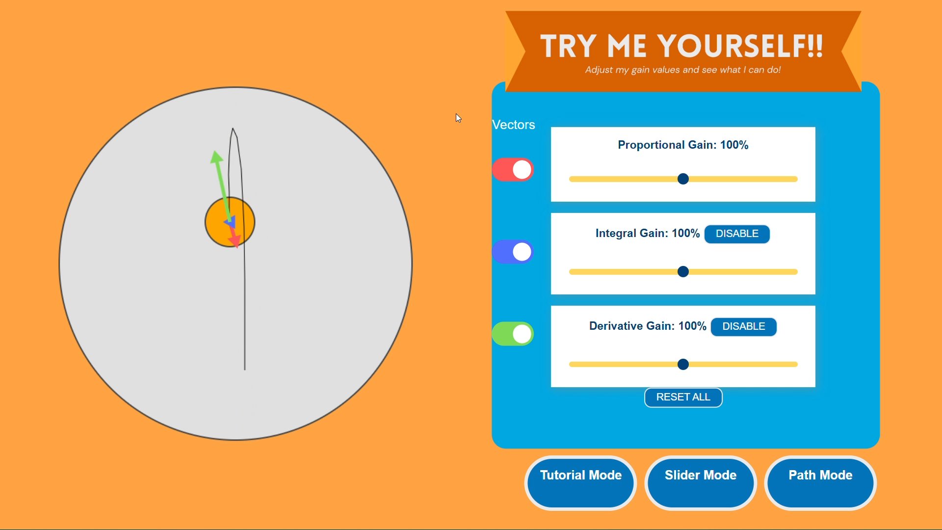
- The main ESP32 receives the ball’s centroid coordinates and runs a PID controller to determine the required platform tilt.
- Using inverse kinematics, the controller computes the motor angles needed to achieve the desired normal vector, with the AccelStepper library providing smooth, coordinated motion across all three stepper motors.
- To eliminate high‑frequency vibration caused by noise in the Derivative term, a dynamic‑D algorithm was implemented that reduces the D‑gain when the ball is near the target.
- A startup calibration routine was also added to measure the platform’s natural tilt and apply corrective offsets, removing steady‑state error caused by non‑level surfaces.
- Motor driver temperatures were reduced by lowering the current limit, which remained effective due to the platform’s low mass.
c, User Interface
- The main ESP32 hosts a local web server through its own Access Point, allowing any device to connect without external Wi‑Fi.
- The interface is built using HTML, CSS, and JavaScript, with a WebSocket connection enabling real‑time visualisation of the ball’s position, PID vectors, and responsive control inputs.
- Users can adjust PID gains, select geometric path‑following modes, or click directly on the display to set a target point.
User Interface